Showing posts with label Wind Energy. Show all posts

Monday, 24 September 2018

Can 100% Renewable Energy Power The World


Every year world use 35 billion barrels of oil this massive scale of fossil fuels dependents pollutes the earth and it were not last forever. The scientist researcher that we consumed 40 % oil according to the present estimate. This rete will run out oil and gas 50 years and coal in an about a century.
On the other side we have abundant solar, water and wind these are renewable resources. So the point is how we can change the world from fossil fuels to renewable sources.
This question rises since a century but it’s hard to answer?

Yet renewable energy provide only 13% of our needs that’s requires 100% that’s inexpensive and accessible. This represent a huge challenge we ignore the politics involve and focus of science and engineering we can better understand the problem by understanding how use energy. The global energy use is a dive race and complex system. The different element require their own solution but now we focus on these to familiar used in daily life.
The electricity and liquid fuel. Electricity powers a lot of things in industry as well as home. Liquid fuels play a crucial role in the transportation.
Let consider the electrical portion first the great news is our electrical advance technology can get energy from every form of renewable source.

 The Sun is the fundamental source of solar energy and continuously accelerates 173 Quadrillion Watts of solar energy at the earth. Its approximate 10000 time more than our need. It is estimated that the surface expands almost 7000 km will be needed to power humanity and our present usage level so, why we not builds that because there are other difficulties like efficiency and transportation.
Firstly the desert are the best places for solar energy but they are located for away from our populated areas where the electricity demand is very high. We transmit the energy by cables through pole that is too expensive and energy loss.

Today the transmitted lines loss the energy 6 to 8% and longer power line dissipate more energy the only super conductor can reduce this loss but they require cool surface not a heated places.
The other solution is we convert the all renewable energy into easily transportable form. We can stores the energy in lithium dry batteries which is low weight and efficient.

There are other sources like hydroelectric, geoelectric and wind energy but they depends upon the location and availability.  


Read More

Sunday, 23 September 2018

How to make money online Pakistan


Now a days Pakistan is emerging country in the field of IT. IT is directly relate to the making money through online. In Pakistan a number of people want to work in spear time as well as a full time. Online working is not a harder task when you have a good skills, knowledge, guidance and commitment for you work.
In Pakistan a lot of method are in market through which we can earn money online like freelancing, online shopping stores, blogging, websites, YouTube, mobile apps and other a lot of services you can provide to make money online. Here we explain some of these method to work online.
Freelancing is the one of the best and trusted source of income. It’s quite simple and depend upon your skills. If you have a specific skill go to the freelancing websites like Fiver, Envato studio, Upwork, Presto Experts and many more. Work on these websites is not a rocket science it’s quite simple. For example you a have good technical Knowledge about a specific Engineering field and you can solves the others problems just go the website put their info about your skills after that needy people contact with you by self. When you get some work and accept the client offer (amount) the decides money move in the third party account. When you complete your task it move in your bank account or reach it to you by other ways.
Online shopping store is the innovation in business field. A Few decade ago you cannot sell your product even a whole country. Now if someone want sell their product in whole world online shopping make it easier without tension of delivery of product as well as collect the price of sell product. Make a website like Draz.pk, Alibaba and Amazon show your product to the world sell and make money.
Blogging is related to the writing skills. It’s a kind of website here you have to write on your interesting topic that other’s like and enjoy. If your post and writing contact not a copy past and unique then Google AdSense give you permission to show add on your blog and when readers read your article adds show automatically through this you can earn revenue.
Website, YouTube and other mobile application have same working phenomena. A programmer built a website or mobile application and upload to the Google paly store or I cloud. When someone download it to use adds shows him and revenue goes in the owner account.
 A lot of many more way to work and earn online in Pakistan but these are the most famous and trending method.


Read More

Saturday, 19 May 2018

Combined-Cycle Generation Process and its working Principle


In the combines cycle power plants we use heat engines that’s work on same source of fuel, converts in to mechanical then into electrical by moving the electrical generator. In this phenomena we use exhaust of one engine used as a fuel of second which seems to be more useful fuel and enhance the overall efficiency of the system. This system is cost effective because we use fuel for heat engine and the waste (e.g., hot exhaust fumes)   produced from the combustion of the fuel used by combining the two thermodynamic cycles so that the overall efficiency improved.
 Brayton cycle is batter for the stationary plants and Rankine cycle commonly used for steam power plant.
Combined cycle power plant consist of following main component.


1:  Gas turbine.

2:  steam turbine.

3:  heat recovery steam generator (HRSG)

Gas turbine


The Gas Turbine essentially comprises a multi stage axial flow compressor section with movable inlet guide vane (IGV), two vertical silo type combustion chambers with several burners, and multi stage axial flow turbine section. The compressor draws in air from the atmosphere, compresses it and
then feeds the compressed air into the combustion chambers. The fuel (natural gas or diesel oil) is injected into the combustion chambers where it is burned together with compressed air. The resulting hot compressed combustion chambers gas flows from the combustion chambers into the turbine section an expands while it drives the turbine. The mechanical enginery of the GT is utilized to drive an air cooled generator as well as compressor section of the turbine. The grid is fed by the generator. The expanded exhaust gases from the GT are fed either to the bypass stack or into the HRSG for further use. The energy given up to the turbine comes from the reduction in the temperature and pressure of the exhaust gas. All these processes make up the Brayton cycle.


GAS TURBINE PRINCIPLE

 A gas turbine works on the basic principle of the Brayton cycle. A Brayton cycle consists of three main components: 
1: A gas compressor 
2:A mixing chamber 
3: An expander/Energy Extractor IDEAL BRATON CYCLE STEPS: 
1-2.Isentropic process - 2-3.Isobaric process - 3-4.Isentropic process - 4-1.Isobaric process
Steam Turbine


The ST is of dual casing condensing type and is operated in the sliding pressure mode from 100 % to 60 % output and in fixed pressure mode below this range. The turbine comprises a combined HP (type D30-
16) and LP section (type N30-25) in which the thermal energy of the steam generated by the HRSGs is converted to mechanical energy in order to drive an air cooled generator to produce electric power. The exhaust steam is condensed in a conventional condenser located behind the exhaust side to the LP-turbine and cooled by the circulating cooling water system which transfers the heat to the atmosphere via a wet cooling tower
Steam turbine principle

Steam turbine works on the principle of Rankine cycle. It has four basic components.

1.     Boiler

2.   Turbine

3.   Condenser

4.   Condenser feed pump


Heat Recovery Steam Generator


Hrsg is heart of combined cycle power plant and a critical link between gas turbine and steam turbine. Hrsg is an energy recovery heat exchanger that recovers heat from hot exhaust gases(1050oF) from gas turbine. It produces steam that can be used to drive the steam turbine in combined cycle power plant.


Read More

Wednesday, 16 May 2018

Why Kite power system is better than wind blade turbine / Bill Gates about Kite theory


The kite Power system currently building 500kw structure these virgin is use 6m vide cord for comparison and equaling to 500 kw wind turbine have diameter 54 m. Wind turbine blade have to strong enough to resist both rotating motion and bending motion and tower have to be strong enough to bear the weight of blade and wind turbine and also need base support in earth or ocean.
In comparison kite power system main component that significant loading. The ground station simply heavy enough to prevent the kites to lift the kites from the ground. This makes the system significant and cheaper.

The study foundation 2016 by the International renewable energy agency find the cost of per megawatt hour energy generated by offshore is 170$ that is expected to fall in 95$ in 2030.
The study conducted by independent KPS the kite power could generate per megawatt hour in 62.5$ by 2020 and 50$ at 2030 it is significantly reduced the cost of offshore 

Gill gates even said that 
10 percent chance the kite power will be the future magic power for the solution of energy crises
The population is increase day by day so there is essential to produce such systems that can use the renewable sources and provide electric energy.    
 

Read More

Tuesday, 15 May 2018

Future of Wind Power ? Kite Power System


On the past decade renewable energy grown from its initiate Now a days clean energy is one of the fastest growing industries despite this continue grow renewable energy generation in united kingdom fell by  1% in  2016 not because of decrease of renewable infrastructure infect the UK capacity to generate renewable energy through by 13.7% it fell by 2016 because have a less wind and rain in 2015. Draw energy from such highly energy source have its drawbacks. So we have to build a new hybrid system like combination of solar and wind in desert.
Wind turbine are typically mounted on mountains to takes advantages of higher wind speed but obviously that's is slim so how that can reach higher to take advantages of higher wind because there is no mountain everywhere.
                                                                      
                                    
Some companies designs and builds some models that’s suspended in the Air with the help of blown take the turbine higher but these gives very little power and not easily scaled because of its size.


So, the other solution is Kites an idea given by the in London Ideas and innovative competitions Kite power system (KPS).
KPS is the UK Company received 5 million ponds investment form organization. This organization invest in new ideas for the future Energy Technologies

This system consist of 2 kites when one  kite go rise  other  lower and produce small amount of energy Theses kites are anchored  with a structure that store the potential energy through 2 cables  and this structure is a turbine that can rotate the generator and produced electricity. When the Air exerted the pressure on the kites and a mechanical force produced this force transform to the turbine through cables.As shown in the figure below


Question:
 what happen when lift of both kite is equal when both reach at same position and not move here (near and far).

These are lift bodies not a drag bodies that are control by a small robot that can control the pitch of the kite by varying the length from front and back and flown on predetermined trajectory.
Read More

Monday, 2 April 2018

Near field Radio Frequency Identification Technologies


This category depends upon the faraday’s principle of magnetic induction for the process of the coupling between the single reader and the series of tag. As a reader is able to pass a large amount of alternating current from the cross section of the reading coil. This also results varying the alternating magnetic field relatively in its cross section locality. When a tag is placed who's cross sectional are is small relatively  and also the smaller coil then the alternating voltage is induced  across it terminal. When this induced voltage is processed through rectification process and is connected to a capacitor bank then a large reservoir of the charge is accumulated through it. which is used to provide the power to the series of tag chip.

Series of tags which use near field coupling transfer the data to the previous  reader with the help of  using load modulation method. As all the current which is drawn through the series of tag coil gradually will provides the increment in poor  magnetic field. This poor magnetic field opposes the main advanced reader’s series of field. The testing coil can predicts this at a small incremental of current which is passing from it. This passing current is directly proportional to the combined. The principle used for this purpose is same as used for that of power transformers.

 As in the transformer effect the primary and secondary coils are connected magnetically not electrically. When the magnetic field through the primary winding increase through specific level then the secondary winding acquires this magnetic field. And it behaves the same role as the tag for the reader. The reader monitors this signal and recovers it. This recovering is done by changing the value of the current. Different types of modulation encodings are established which are based at the complete number series of registers and of ID bits.
Near-field coupling is completely a best technique to implementing practically a number of passive radio frequency identification system. With its advantages the narrow field also has some disadvantages and restrictions. The periodic range used  for  this purpose is approximately c/2πf. In this periodic approximation c shows a constant value which is also called  speed of light. Where f represents  the frequency. So when the frequency of increases automatically then the measuring distance decreases upon which the field coupling is depending.
 Moreover a specific limitation is required for the energy which is existing as the induction. This induction is the function of distance. It is connected with the reader coil. In this case the dropping factor for the magnetic field is near 1/r3. In this factor the r is representing the value of distance between or the separation of the tag and the reader. It is along the direction of center line. This center line is mutually perpendicular to plane of coil. In this case more ID bits are also required.


By the way the near field radio frequency communication system also has some restrictions and limitations physically. For this purpose the range used is near about c/2πf and it has magnetic effect.
Read More

Sunday, 12 March 2017

FIR FILTER

Read More

Thursday, 9 March 2017

PCB Designing

Read More

Sunday, 26 February 2017

Transformer moisture measurement Condition Assessment Techniques For Electrical Equipment

Transformer moisture measurement


Water In the transformer cause to produced odd substance, also decrease the insulation of break down. When a large amount of water content of paper as a result bubbling produced and also increased the chance of dielectric breakdown. There are three main source from which the water comes in the transformer: residual moisture in the thick structure element login from the atmosphere and cellulose, oil increase the speed of decomposition the amount of moisture in the transformer is less than 1 %, but the target value is 0.5 % when the new transformer is formed and ready to use.
Thick insulation component, plastic1 are the component in which the amount of moisture is 2 to 4 %. At the time of repair or service, these moisture seeps into the transformer oil when increasing the content of water in the rarer insulation structure. The water present in the major sources of transformer pollution. Three processes are directly related them firstly amount of water observed in the insulation from the air at the time of installation and repair work ,the second one is its natural that moisture flow from high concentrations to low concentration ,the same thing is to happen in the transformer the concentrations of water in the atmosphere is higher then the concentrations of the transformer oil in the tank, and the third one is that a large amount of viscous wet air flow inside the transformer that caused the difference of pressure in the atmosphere and the pressure in the tank
A minimum amount molecules flow inside them but the major sources of water penetration inside are air flow through the poor sealing like through the bushes sealing points and loop which moderate the temperature inside etc., all this is happening due to the pressure difference. If the transformer has improper sealing or the instantly only decrease of pressure then a large amount of water like rain water penetrate in the transformer in very minimum time.

Methods and instrumentation for moisture measurement
In the transformer industry, the term “moisture” is used to differentiate the how much amount of water is dissolved in the transformer oil or the amount the water absorbed in the paper.
Sometime the term water or water content is used commonly but these are synonyms of each other and use to explain the same theory. In the transformer, the water is presented in the different parts of the insulation system. Water is the water it makes its own way and so it is present in solid insulation or dissolved in the oil, sometime it is found at core or bottom of the transformer as the form of liquid water.
There are a number of methods and instruments are used in the market for the measuring the moisture. When we want to calculate the water content in oil or polymer relative humidity or relative saturation sensors is frequently used. When we calculate the relative saturation of oil can easily get the absolute moisture which is expressed in (ppm).

Water content of paper insulation
A new concept of measuring transformer moisture was introduced which is based on the water in paper activity method. The different aspect of water in paper activity used to measure the amount of moisture in the both new one or old transformer insulation system. Another term “active water content of the paper (WCP)” was also determined. This concept of WCP shows the relation water in paper and oil in the insulation of transformer. The figure shows the same parameter of water in paper activity to the active water content of paper.


There is another way to determine the WCP of paper insulation in a paper-oil insulation. System and equilibrium chart of moisture is used.
Another chat of moisture equilibrium is published in 2 and earn very fame which is shown in the
figure.

In this show the difference between the water content of oil (WCO) which is expressed in oil, the percentage moisture of paper and the temperature.
Assessment of moisture in an operating transformer
it is usually said that operating transformer is not in moisture equilibrium. So the both of these charts of moisture equilibrium which is shown in the figure cannot me utilize directly for moisture. Due to this another method of accessing the moisture in the transformer is developed which is based on the Monash water in paper (WIP) algorithm. This method consists of three steps.

 Assessment of true oil relative saturation in the transformer
Assessment of the water-in paper activity (AWP) for the transformer oil
Assessment of the active water content of the paper (WCPA) as a
function of AWP and temperature. (Roizman, 2002)
On the basis of WIP algorithm, a software application is developed as the name of Transformer Moisture Monitor (TMM). The TMM uses neuron-fuzzy computing to determine moister sensor output. The TMM get data form via sale HMP228 Humidity and temperature transmitter.

The HMP228 transmitter gives on line measurement of the transformers moister and temperature.
Transistor gives information time to time and indicates earlier when the transformer has some issue.
Vaisala;s microprocessor based HMP228 Transmitter has the high speed of execution, reliable easy to use and maximum accuracy. The earlier model of HMP228 Transmitter can measure only average water solubility in the transformer mineral oil. The water ionization in the oil depends on the temperature it will increase as the temperature increase. Transmitter measured the water activity and cultural ppm output. One of the benefits of the water activity is that indicate the directly rather than the oil is too moist. The activity of water measurement depends upon the aging or temperature of the oil.


Read More

Friday, 24 February 2017

PD (partial discharge) Assessment Techniques For Electrical Equipment

Condition Assessment Techniques For Electrical Equipment

Condition assessment techniques are the very famous method to look after the electrical equipment. These are used to identify the significant changes which are caused by many problems and prevent the failure. Due to these techniques, we check the tool as scheduled. There is a number of the method but here I explain two techniques.
•            PD monitoring
•           Transformer moisture measurement

PD monitoring

The PD (partial discharge) is used many years for test and investigates the insulation system design and check the level of quality of new equipment. In the last 20 years the use of partial discharge increase dramatically.Now a day these are used to diagnose the present condition of electrical insulation in the using apparatus. It is used in like switchgear, transformer, cables, windings of the stator in the generator and as well as in the motors. PD has many qualities so that the use of partial discharge increase day by day due to the sensors which are used in it is low cost, electronics as well as the memory is effected its popularity. The use of ultra wide band detection and the acutance in the measurement of the partial discharge in the presence of noise are the methods that cause its (PD) popularity.    
Partial discharge is produced due to electrical breakdown of a gas (e.g. air) in the highly un specified electrical field. Partial discharge is like a small electrical spark. The partial discharge will degrade the level of organic material and sometimes cause the big fault and stop working of electrical insulation if the void is present in the liquid or solid of organic. The nature of partial discharge is destructive for over previous 70 years in the oil-paper insulated high voltage cables as well as the other high voltage equipment. The insulation of different instrument is made of organic materials like oil, paper, polyester .polyethylene, rubbers, polyester.We have to pay full attention to formed the insulation system of high voltage cables, transformers, capacitors and switchgear that not include the little amount of void in the region of electric high stress.
PD is also caused to destroy earlier the electrical apparatus. At the result of the high-temperature operation, voids mix within the epoxy mica insulation or oil-paper insulation due to this localized electrical stress on insulation surface and discharge in the air.  The presence of Partial discharge cause the environmental mechanical and thermal aging processes.  
There is no doubt that the partial discharge measurement method is devolved since 1930. There are many reasons to measure the PD design test. It is simple to find the presence of PD for new insulation system under the normal operation.
Quality Assurance: it is done to believe that partial discharge is not the presence in the newly formed insulation system.
Diagnostic test: this is suing to identify the fault due to thermal, cables the electrical and mechanical stress during the working of insulation system in the transformer, switch cables the and aim and purpose of these tests to find the PD level. If the amount of PD Level is too high then it indicates of failure of system insulation permanently.
There is a number of a researcher who finds the method of investigating the partial discharge during 1950 to 1980 like Bartnikas, Kelen, Kreuger. These top researcher introduced a different method to show the data and identify the PD. After a long time, these methods are used to measure and detect the PD in laboratories and industries no a days.
the most famous researcher  Bartnikas, Kelen,  Kreuger, Gulski and other prolific researcher take a step forward and formed the advanced technology to measure the partial discharge.to the point that off the line and on line. These online techniques are used in high percentage transformers machines cables and switchgear that are working in the world industrial countries.

Features of PD measurement systems

A famous researcher Bartnikes recently summarized the theory of PD, calculation technology, and a brief overview of the partial sensor.

Sensors (Coupling Devices)

electron move very fast form one side of gas-filled void and pass another side when the partial discharge waves formed. The time of these pluses is nanosecond and the electron moves at the speed of light. The e- has charged and each discharge generates current waves I = DP/DT. A positive charge also flows in opposite direction .the current generate a disturbance and at conclusion current and voltage flow outside the PD site.  At this time the frequencies reach at several megahertz the Fourier transform of a current shown.
PD pulse current can easily identify by any sensor that can sensitive the high frequency. When we did an off line test then we use a very high voltage capacitor which is connected to the terminal of high voltage of the test object.

Partial discharge can also be detected by the following

Electromagnetic Radiation
Acoustic noiseVisible and UV light

Electromagnetic radiation can be measured by RF antennae.
Due to Discharge on insulation system electron and ion formed a gas pressure that can be identified by the acoustically.
The final famous process is detected PD uses the fact that the light that’s transparent the energize molecule and emit energy after the discharge. When they pass through the spectrum a light is produced and a naked eye can easily detect these rays of light on the surface f PD.

Detectors

partial discharge is detected by the voltage signal, PD pulses current convert into the voltage signals because it is easy to detect the voltage signal rather than current. The conversion takes place via a resistor or R L C detection impedance is used.RLC identify the method of resistance is very famous, the total number of ions and electrons and ions that are bombarding the insulation surface is directly proportion the failure or decay of organic insulation surface and if the rate of discharge is greater than the decrease of insulation is faster.

Detectors


Many types of instruments are in the market to calculate the signals which are from the Partial detector and sensors combinations.

Analog oscilloscope was most famous and reliable tool to calculate the PD showing signals it’s about last twenty years ago. The pluses were calculated by the PC (vertical scale) versus the AC phase position. The bandwidth of the oscilloscope at that time is very limited and the pulses of PD appears on the screen of the oscilloscope for very minimum time so it was very difficult to calculate the accurate magnitude of the pluses. The rate of repetition of partial discharge pluses is not measured able, last 20 years are very important to the development of the instruments in the field of PD deduction. Now a days all the instrument are digital infect the instruments used before was totally analog. Due to the digital world, we can easily enable to the separation of noise, continuous online PD monitors, PD site Location and practical. 

Statistical Analysis


This approach uses a skew, standard deviation and kurtosis to identify the figure and location of positive and negative partial pulses with respect to the AC phase angle. Every partial discharge mechanism and each type of noise have unique set of mean phase angle, standard deviation, skew, and kurtosis. (G.C.Stone, October 2005) This was the first researched automates pattern to identify the method.PPA plot gives all raw data .this is shown in the figure.


        Pulse phase analysis plot of the pulse magnitude versus AC phase position   

  with pulse count rate in pulses per second represented as color.
Partial discharge ratio changes as the pattern of PD. The pattern shape differs in the mean skew and kurtosis with respect to the phase angle. Which is shown in the figure.

Read More

Wednesday, 16 November 2016

Wind Farms for Wind Energy

Wind Farms:

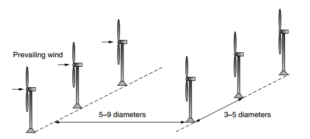
Now the point is how many wind turbine would be install at this place. If we install all the wind turbines near each other they effect each other. For example the upwind turbines effect the amount of wind received which is located downwind.
Due to upwind the velocity of wind slow down which effect the speed of rotor machine’s located downwind we can minimize the effect by install the turbines some distance.

             Relation b/w rotor diameter & array efficiency
Performance of system decrease when all located too close.
The above figure show the effect of array efficiency with respect to the tower spacing. Here 4 types of array mentioned which show different number of turbine and area. For example in 2 × 2 shows array consist total 4 turbines have equally distance each other, 8 × 8 show’s that 64 number of turbines installed in the square area, 6 cross 6 show 36 wind turbines in equally spaced area and 4 × 4 has 16 turbines.
Number of array is inversely proportion to the efficiency of the wind turbine.
From the previous figure and theoretical study result tells that the space between the tower in the row recommended is 3–5 rotor diameters each one and the distance between row of wind turbines approximately  5–9 diameters.


Spacing b/w tower and rows
Read More

Friday, 11 November 2016

Different Method Of Speed Control For Maximum Power In WIND Turbine


Importance of Variable Rotor Speeds

For the Speed control one of the important is variable rotor speed.
Rotors reach high efficiency having minim no. Blade.
In this picture show that the rotor efficiency denoted by Cp. Rotor efficiency depend upon the tipspeed ratio in short form TSR.  The best TSR is consider the around about 4-6(simply when blade of wind turbine moves 4-6 times of air velocity). As the velocity of the air rotation of blades change.

Show blade efficiency directly proportional to the wind speed.


Graph show that the effect of rpm and plotted between wind speed and blade efficiency. Hence clearly show the effect speed of the rotor with respect of Cp(blase efficiency) 

Here its show that when the rotor speed increase (20-30,30-40) the electric power also increase. 


Pole-Changing Induction Generators

For this method we can control the speed of generator or motor. No of pole play important role for controlling the speed. In the induction generator poles located on stater and from external connection we can change the speed of generator with out changing in the rotor.
3600 rpm produced when the frequency 60 Hz and no. Of poles is 2.
A number of house holed devices such as exhaust fan, washing machine can be ran in different speed using pole changing phenomena.  

Multiple Gearboxes

We can also control the speed by using the more then gear boxes. For example we use two gear box each of gear box attach separate generator. Combination form like that a gear box for low wind speed connected to generator 2nd gear box designed for high wind velocity plus generator.

Indirect Grid Connection Systems 

When speed of wind change the movement of blade change with respect to wind. When the synchronous or induction generator produces extra energy then how we can handled it.
we can add this extra energy to the grid system but we can’t add this directly because frequency factor involve. Our grid system has 50 -60 HZ energy but the output of generator we don’t have same frequency. A process given below in the figure to add this energy in the grid system.


Rectifier, inverter and filter to reach 50 or 60 Hz frequency

In the above section we talk about higher level energy section but if we have a small energy production system like 5 to 10 kw then.
We can control the speed and save the energy. We can control speed by adding extra load. When we add this the more load generator required more rpm and the wind turbine due to load slow down.
If we add extra battery bank then store this energy and utilize after all.  

Read More

Thursday, 10 November 2016

TOWER HEIGHT


TOWER HEIGHT

It is very important to know that wind is not running smoothly and constant near the earth surface so its very necessary to high flow of wind to get maximum rotor speed and try to reach required rpm.
But the question is How to get maximum wind speed.
 Height of tower
 Shape of wings
 A suitable Generator etc …
IMPACT OF TOWER HEIGHT
  Height of tower is very important. The velocity of wind is badly reshape by the variation of earth surface, a bit friction also effect when wind moves smooth surface as well as the clam sea. Few hundreds above  the earth surface obstacle disturb the wind like forest and building irregular the the flow of wind. We know that speed of wind is high and constant at height. This equation show describe the relation of height and roughness of surface.
V/Vo = (H/Ho)^alpha


Velocity denoted V.
Height of tower denoted by H.
Ho commonly used 10.
Vo wind speed at the height of Ho.
Alpha is fraction coefficient.


The lowest friction coefficient is the smooth flat earth which is 0.10. High crops and country side consider to be medium coefficient. The height’s friction coefficient considered to be large buildings and hills.  

Z= roughness length.
The roughness of water surface is 0.0002 m which is lowest and the heights is 1.6.

The speed of air very different with in flat area and hilly area. In the low wind speed area vertical blade shape of wind turbine very preferable. There are on lot of benefit of vertical shape of wind turbine.
ØVertical shape blade moves rotate in very low velocity.
ØFor the design of small level wind turbine vertical shape of blade used.
ØThey can move even when the direction of wind top to bottom.
ØVertical axis wind turbine works for all direction of wind doesn’t matter what is the direction of wind.
ØMost important thing for vertical wind turbine is they do not concern of tower height.

Read More